|
|
| |
| 상품 목록 |
|
 |
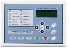
Digital Engine Controller Unit iECU6220
( Model Number : iECU6220 )
|
|
|
|


|

|
 Click to enlarge image Click to enlarge image |
|
The newly developed iECU of Pesco Corporation has been designed to meet modern taste in design of users and engineered to be userfriendly with easy to operate controls.
1.Application)
i ECU is applied to various monitoring and controlling requirement of all types of generatosr and engine pumps.
2. Specification
Display : AC Current Voltmeter, Frequency Meter, Tacho Meter, DC Voltmeter, AC Ammeter, KW Meter, PF. KWH. Fault Status Indicator, Operation Mode Selection Indicator, Operation Status Display
Battery Charger : DC Voltmeter, DCAmmeter (Optional)
Engine Control Meter: Oil Pressure Meter, Water Temperature, Operation Hour Recorder, Engine Speedometer
Generator Control Part S/W : Voltmeter(Displays High Volage and Line Voltage), Current Display, Displays Amount o Voltage, Displays Voltage Consumption
Circuit Breaker : Users can select and apply functions such as Low Oil Pressure, Over Speed, High Temperature, Over Current, High Voltage, Low Voltage, Low Speed, Emergency Stop.
Front Panel Fault Indicator Lamp: Over Speed, Over Temperature, Main Power Sensing Lamp, Generator Sensing Lamp, Automatic Operation, Manual Operation, Emergency Operation, Emergency Stop, Emergency Alarm, Operation Status Lamp
Control Parts : Battery Charger, AVR, Voltage Regulator(VR)
3. Structure
Dimension : 240 mm(W) × 172 mm(L) × 62 mm(H)
Color : Front Panel Color : Gray
Box : White
4. Main Functions
Various engine problems(Over Temperature, Over Speed, Low Oil Pressure, Over Voltage, Low Voltage, Over Current, Emergency Stop, Low Speed etc) can be adjusted to suit requirements of users. Engine Stop and Circuit Breaker Trip maybe optionally selected for application.
When any error occurs, error occuring part and the time will be automatically saved for reference.
When an error occurs, content of the error will be indicated on the screen.
User may select Auto Start from 0 ~ 10 times. (0 ~ 30 seconds)
When the main power source fails, engine will be started after selected time lapses. (0 ~ 60 seconds)
When the main power source returns, Engine will stop when the selected time lapses. (0 ~ 60 seconds)
When the main power source returns or when main power source fails, circuit break may be inserted or removed after selected period lapses. (0~60 seconds)
When the engine problem occurs or when failed to run, restarting of engine will not be possible without pressing the RESET button.
Main power sensing may be done using electric contact or electric power source.
Possible to control start and stop, circuit breaker insertion and isolation using Remote Controlling.
Oil pressure, MPU can be controlled using generator frequency while running the engine.
Possible to control using Remote controll (Optional).
Easy installation with One-Touch method.
Possible to identify all status of engine part and generator part using the display.
5. Operation Preparation
Install the iECU to Generator or Fire Pump Panel.
Following the attached blueprint, correctly connect Panel and Engine Generator using wires provided.
Check fuel, water and oil.
Connect the main power source or electric contact point to automatic operation.
Connect the battery.
AUTO OPERATION
Generator can be easily operated by sensing main power source status using electric contact point or electric power source.
When engine pre heating is required prior to the automatic operation, the user can select and operate using pre-heating mode.
Generator can be controlled by sensing power in or out of main power source, at the same time, circuit breaker insertion and isolation may be simultaneously used. (Semi-Automatic loaded, ACB External, ATS External etc can be controlled.)
MANUAL OPERATION
Automatically transfers to manual operation by pressing Operation Selection Button 1 time, Pressing 2 Times = Automatic Operation, Pressing 3 Times = Remote Control
Selecting Manual Operation then press the start button once to enter Pre-Heat Mode, press again to start the engine.
After starting the engine, circuit breaker insertion and isolation may be done.
ETR/ETS may be selected following the engine condition and operation by selecting various engine switchs and converters maybe done.
If start button is still pressed even after engine start, engine would be protected for starter motor isolation time is automatically controlled.
REMOTE OPERATION
By selecting operation selection button located at the front of the i ECU panel to turn on the remote start switch, the engine will be started. When the switch is turned OFF, the engine will stop and enter in to Start Waiting status.
Circuit breaker ON/OFF may be remotely controlled after the engine starts.
Window control, intranet and internet control are supported.
Remote control may be done by selecting RS485 or RS232 communication.
Remote controll is possible even through the internet.
|
|
| [ 연락처 정보 ] |
 Company Company |
(주)피스코 |
 Address Address |
경기 고양시 일산구 장항동 617-7
(우:411-380) 한국 |
 Phone Phone |
82 - 31 - 9084071 |
 Fax Fax |
82 - 31 - 9084073 |
 Homepage Homepage |
www.pesco21.com |
 Contact Contact |
유병혁 / 대표이사 |
|
|
|
| |
|
|
|
|