|
|
| |
| 상품 목록 |
|
 |
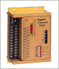
Engine Controller Unit
( Model Number : ECU )
|
|
|
|


|
|
 Click to enlarge image Click to enlarge image |
▒▒▒▒▒▒▒▒▒▒▒▒▒▒ Welcome to Pesco21 ▒▒▒▒▒▒▒▒▒▒▒▒▒▒▒
 |
product
:E.C.U |
| |
|
|

|
|
|
|
 Application Extent Application Extent
Basic Constitution
Structure
Feature
Detail
|
dwf-view
down
Dimension
|
 |
| 1.Application
Extent |
| |
| This
product is applied to automatic, manual, starting, stop
and protection of diesel
engine. |
| |
▲
top of page
|
|
2.
Basic Constitution
|
| |
- Input Power:12VCD~24VCD±25%
- Speeding Sensing
- Detection Mode of Voltage:0~75Hz, 7~300VAC(No.1
SW ON)
-Detection Mode of MPU:0~7,000Hz, 4~30VAC(No.2 SW
ON)
- Out of METER
- TYPE1 : RPM FS 500μA (No. 5 SW ON)
- TYPE2 : Hz/RPM FS 500μA (No. 7 SW ON)
- TYPE3 : RPM FS 5V (No. 6 SW ON)
- SWITCH
- Signal Input"+"(No.9,11 SW ON)
- Signal Input"-"(No.10,12 SW ON)
|
▲ top of page
|
|
3. Structure
|
| |
- CPL : Main blackout
signal(YELLOW) input power "+"output)delay
time adjustable
- PHL : Running ready
signal(YELLOW) Automatic starting delay
time adjustable(0~30 SEC)→PH+(input
power"+"output)
- ARL : automatic starting
signal(GREEN) Automatic starting delay
time adjustable()~30 SEC)∴Automatic running time
PS : Usable engine stop
except engine trouble
|
▲ top of page
|
|
4. Feature
|
| |
- Automatic and manual starting
- Engine protection(over speed, high
temperature, low oil press)
- Engine stop by out signal(over voltage,
low voltage)
- Double protection by IDLE SPEED
and oil press
- Dual run sensing signal (standard:
Voltage, option: MPU)
- Usable unrelated engine type(ETS-SW3,4
ON, ETR-SW5 ON)
- Dual engine pump using signal (standard:
voltage, press)
- Durable against damp and dust by
silicon molding
|
▲ top of page
|
|
Detail
|
| |
| 5.
Indication LED&Protection Circuit |
| |
- CPL
: Main blackout signal(YELLOW) input power "+"output)delay
time adjustible
- PHL
: Running ready signal(YELLOW) Automatic starting
delay
time adjustible(0~30 SEC)→PH+(input power"+"output)
- ARL :
automatic starting signal(GREEN) Automatic starting
delay
time adjustible()~30 SEC)∴Automatic running time
- OCL :
Running fail signal(RED) 3 Crank attempts with interval
7sec
cranking and 7sec→ OCL(input power "+"output)
- OSL
: Over speed signal(RED) Automatic starting over speed
set
(input power "+"output)→OSL(input power
"+"output)
- WTL
: Cool water high temperature signal(RED) Automatic
starting
close cool water high temperature switch → WTL(input
power
"+"output)
- OPL
: Emergency stop signal(RED) Automatic starting close
emergency stop switch→OPL(input power "+"output)
- EPL
: Emergency stop signal(RED) Automatic starting close
emergency stop switch→OPL(input power "+"output)
- PS
: Usable engine stop except to engine troble
- RUN :
Engine starting signal(GREEN) Automatic starting over
Idle
speed(600rpm)
- SOL
: Fuel valve running signal(YELLOW)
|
▲
top of page
|
| 6.Regulator |
| |
- OST
: (Over speed test) Button of over speed test.
Button push down, indicate to maximum scale of RPM
METER
regardless of present speed.
Automatic starting run of over speed protection circuit
of OSL
and engine stop.
- O/S
: (Over speed adjustment) Regulator for adjustment
of over
speed protection circuit running.
Setting up ☞ 1800RPM(60Hz)~2100RPM(72Hz)
- RPM/OST
: Regulation for adjustment RPM(Hz) METER ADJ.
RPM(Hz) METER
Usable over speed test (Just
as increase meter output at will)
- 27T
: Time adjustment
Automatic starting delay time adjustable (0~30sec)
Running of preheating circuit
- 62T
: Automatic stop delay time adjustable (0~180sec)
|
▲
top of page
|
| 7.Constitution
of input&output terminal |
| |
- CP1,CP2 : Main power's voltage blackout
sensing signal input
terminal
- BP+ : BATTERY "+" input
terminal
- CNT : Main power's voltage blackout
sensing signal input
terminal (CONTECT) (CP1,CP2↔AC220V↔ATO Terminal)
- ATO : Automatic starting signal "+"input
terminal
- MNU : Manual starting signal "+"input
terminal
- BP- : DC POWER "-"input
terminal
- STT : Engine running signal output
terminal (Voltage output
MAX:10A)
- STP : Engine stop signal output terminal
(Voltage output MAX:10A)
- OPS : Lubrication press switch input
terminal
- WTS : Cooling water temperature switch
input terminal
- EPS : Emergency stop switch input
terminal
- PH+ : Preheating output terminal(Voltage
output MAX:1A)
- OCL : Running fail lamp output terminal(Voltage
output MAX:1A)
- OSL : Over speed lamp output terminal(Voltage
output MAX:1A)
- WTL : High temperature lamp output
terminal(Voltage output
MAX:1A)
- OPL : Low oil press lamp output terminal(Voltage
output MAX:1A)
- EPL : Emergency stop lamp output
terminal(Voltage output MAX:1A)
- BZ+ : Buzzer output terminal(Voltage
output MAX:1A)
- 14X: Low speed contact point output
terminal(Voltage output
MAX:1A)
- LTS : LAMP TEST terminal (Lamp Voltage
Input)
- TM+ : RPM METER output terminal(Choice
of Meter kind)
- SS1,SS2 : Engine starting signal
input terminal(standard:
Voltage AC220V, option: MPU)

<drawing
1>
|
▲
top of page
|
| 8.Basic
Function Test |
| |
|
1. Input&Output
terminal of E.C.U. is connect to circuit like drawing1.
2. Before E.C.U. test, each product
&E.C.U. state set up like next.
- SW1 : OFF(Automatic&manual option
switch)
- 26W : OPEN(26W: high temperature
switch)
- 63Q : CLOSE(63Q: oil press switch)
- EPB : OPEN(EPB: emergency stop switch)
- DIP SW : Right choice of engine running
signal, solenoid action,
protection switch polarity
1)Voltage, ETS, FS500uA, "-"signal input
ON--1..3.4.6.10.12. OFF--2.5.7.8.9.10.
2)MPU, ETR, FS5V, "+"signal input
ON--2.5.7.9.11. OFF--1.3.4.6.8.10.12.
3. MANU Function Test
3.1 Select to SW1 in drawing1 ∴5X
is running through 12X
, 26WX, 63QX, "b"contact point of EPS.
solenoid(5S) is running through voltage output of
STP terminal
(ETR TYPE) 88X is running through 14X"b"contact
point
(No running oil press switch of 63QY"a"contact
point)
Constituted starting circuit through voltage output
of SST
terminal
▶"a"contact
point function of 63QY- started engine&increased
oil press Prevented interception of starting circuit
▶SS1&SS2
terminal starting signal input- running of 14X
(600±500RPM)STT output interception through 88X off
Running stop through double interception of starting
circuit
3.2 .Automatic starting PUN LED of
E.C.U. by engine starting
signal input
After automatic starting PUN LED, 63Q(oil press switch)
must
open within 7sec.
3.3 Engine stop
▶ETS(ENERGIZED
TO STOP): In case of stop, fuel line closes.
▶ETR(ENERGIZED
TO RUN): In case of start, fuel line opens.
ETR: 5X off by SW1 off ∴ interception voltage of STP
Fuel
line 5S off ∴ engine stop
ETS: STP voltage output for ≒15sec. by SW1 off Feul
line
5S on ∴engine stop, 5X off
4. AUTO Function Test
4.1 (SW1 set up AUTO) Supplied main
power's voltage of
CP1, CP2 - STANDBY state of E.C.U.
Interception of main power's voltage CP1, CP2 -Running
of "a"
contact point 62X after 0~30sec.
Running of 5X and 88X like manual
★ PH+ voltage output & Running
of 23X for automatic starting
of PHL LED
★ PHL LED & 23X put out by automatic starting
of PHL LED
4.2 62X is 3 crank attempts with starting
of 12sec and stop of
8sec 62X is continue "on" like manual by
engine starting signal
input
In case without engine starting signal input for 3
crank
attempts-62X stop and starting fail
4.3 Engine normal starting - Automatic
starting CPL, ARL, RUN,
SOL LED
4.4 (Engine normal starting) main
power's voltage supply of
CP1, CP2 -have a time(0~3min.)of engine cooling
engine stop by 62X off
▶Sensing of 27X contact point by main
power's voltage blackout
signal-connect 27X "b"contact point of CNT&ATO
terminal
▶Don't need connection of CP1, CP2 terminal.
▶ATO&CNT terminal closing-start
ATO&CNT terminal opening-start as generation electricity
signal
▶Detection power and press at same time by using engine
pump
▶Refer to below table when engine pump control uses
|
▲
top of page
|
| |
 |
|
|
|
|
|
|
| [ 연락처 정보 ] |
 Company Company |
(주)피스코 |
| Address |
경기 고양시 일산구 장항동 617-7
(우:411-380) 한국 |
| Phone |
82 - 31 - 9084071 |
| Fax |
82 - 31 - 9084073 |
| Homepage |
www.pesco21.com |
| Contact |
유병혁 / 대표이사 |
|
|
|
| |
|
|
|
|